
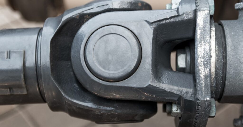
The driveshaft arrangement must accommodate mechanical movement, rotational speed, and installation constraints without introducing excessive vibration or stress. Selecting an unsuitable assembly leads to premature joint wear, damaged connections, and unexpected equipment downtime. Choosing the right driveshaft configuration involves comparing available designs against the equipment’s operating requirements to determine which arrangement delivers reliable power transfer.
Identify the Equipment’s Driveline Requirements
Before comparing driveshaft designs, technicians must establish how the equipment transfers power between its transmission and driven components. Underground loaders and haul trucks experience substantial torque demands during loaded acceleration, steep climbs, and repeated changes in travel direction. These operating conditions influence the strength and construction of the driveshaft assembly.
Maximum torque and rotational speed provide a starting point for selecting an appropriate design. Transmission ratios influence the torque reaching the driveshaft, so engine output alone doesn’t establish the assembly’s required capacity. Manufacturer specifications help technicians identify suitable component ratings while accounting for the equipment’s intended duty cycle.
Compare Single-Piece and Multiple-Piece Driveshafts
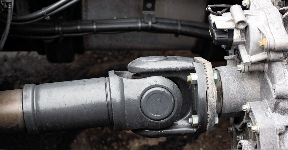
The distance between powertrain components determines whether one shaft assembly provides sufficient rotational stability. Single-piece and multiple-piece arrangements offer distinct approaches to transmitting power across that distance.
Single-Piece Driveshafts
A single-piece driveshaft connects two drivetrain components through one continuous shaft assembly. This arrangement suits applications where the installation distance permits the shaft to operate within its specified speed and load limits. With fewer connecting joints and no intermediate bearing assembly, it presents a relatively straightforward installation.
However, shaft length influences its susceptibility to vibration at elevated rotational speeds. Evaluate the relationship between shaft diameter, operating speed, and critical speed before selecting a single-piece design.
Multiple-Piece Driveshafts
When the distance between drivetrain components exceeds the practical limits of one shaft, a multiple-piece arrangement provides another option. Intermediate shaft sections and center bearings divide the distance into separate spans, addressing rotational stability concerns associated with an excessively long unsupported assembly.
These configurations introduce additional universal joints and mounting points that require precise alignment. Center bearing placement must accommodate the equipment’s structural layout, and each shaft section must satisfy its individual operating requirements.
Evaluate Universal Joint Configurations
Powertrain components frequently operate on separate centerlines, requiring joints that transmit rotation through an angle. The appropriate joint arrangement depends on the angular relationship between connected components and how that relationship changes during operation.
Single-Cardan Universal Joints
A conventional single-cardan universal joint accommodates angular movement between connected shafts. However, when the joint operates at an angle, its output experiences rotational speed fluctuations during each revolution. A correctly arranged two-joint driveshaft compensates for those fluctuations when the operating angles and yoke orientation meet the applicable design requirements.
This configuration suits many applications with controlled operating angles. Technicians need to measure both ends of the assembly because improper alignment introduces vibration and increases bearing stress.
Double-Cardan Universal Joints
A double-cardan arrangement places two universal joints close together within a connecting assembly. Properly designed arrangements coordinate their movement to accommodate certain angular relationships that present challenges for conventional single-joint connections.
These assemblies have specific centering, lubrication, and operating limitations. Technicians must verify manufacturer approval before selecting this arrangement, since its suitability depends on the complete drivetrain design.
Account for Operating Angles
The position of the transmission relative to the axle determines the angular relationship a driveshaft must accommodate. Even when components appear aligned, vertical or horizontal offsets introduce operating angles at the universal joints.
Technicians should measure these angles under the equipment’s normal operating conditions and account for movement under load. With conventional two-joint arrangements, appropriate joint angles and yoke phasing minimize rotational irregularities. Manufacturer limits ultimately determine whether the proposed configuration suits the equipment’s operating speed and alignment.
Consider Suspension Articulation
Underground equipment encounters uneven ground that changes the position of connected drivetrain components. Axle movement alters joint angles, potentially pushing a previously acceptable configuration beyond its operating limits.
Evaluating the full articulation range reveals whether the selected joint arrangement accommodates those changes. Measurements taken with the equipment stationary provide useful information, but technicians have to consider loaded conditions and suspension movement before finalizing their selection.

Determine the Required Shaft Dimensions
Driveshaft length affects both installation compatibility and rotational performance. Technicians must measure the distance between connecting interfaces according to manufacturer procedures, accounting for the dimensions of the selected joints and yokes.
Shaft diameter and construction influence torsional capacity and resistance to vibration. An assembly operating near its critical speed risks substantial deflection, even when its components meet the required torque rating. Comparing calculated operating speeds against manufacturer limits establishes whether the proposed dimensions suit the application.
Select the Appropriate Slip Joint Arrangement
Changes in the distance between drivetrain components require a means of accommodating axial movement. Slip joints use telescoping splined connections to permit controlled extension and compression as the equipment operates.
The selected configuration must maintain adequate spline engagement at maximum extension and sufficient compression travel at minimum length. A slip joint that reaches either limit transfers unwanted loads into adjacent components, potentially damaging bearings or connection interfaces. It’s essential to match the assembly’s travel capacity to the equipment’s full movement range.
Verify Flange and Yoke Compatibility
Mechanical connections determine whether a driveshaft fits the transmission and driven components correctly. Flange diameters, pilot dimensions, bolt patterns, and yoke designs must correspond to the original equipment specifications.
Incorrect connections introduce alignment problems or insufficient engagement between mating surfaces. Therefore, technicians should verify part numbers and examine existing interfaces for wear before selecting replacement assemblies. Proper hardware and manufacturer fastening specifications maintain secure connections under repeated torque loading.
Consider Driveshaft Balance Requirements
Even a correctly sized assembly develops vibration when its rotating mass lacks proper balance. Imbalance generates centrifugal forces that increase with rotational speed, placing additional stress on joints, bearings, and connected components.
Driveshaft repairs and modifications sometimes alter the assembly’s weight distribution. Professional balancing verifies that the completed assembly meets applicable requirements before installation.
Confirm the Configuration Before Installation
After identifying a suitable arrangement, technicians must compare its specifications against the original equipment documentation. Confirming torque capacity, operating speed, joint angles, and installation dimensions establishes whether the complete assembly suits the intended application.
Existing wear patterns provide additional insight. Repeated universal joint failures or unusual vibration might indicate an alignment problem or an unsuitable configuration. Reviewing these conditions before replacement prevents maintenance teams from repeatedly installing components that encounter the same mechanical problems.
Protect the Driveline’s Reliability With the Correct Configuration
The right driveshaft configuration needs to accommodate the equipment’s operating demands. When an existing assembly experiences recurring failures, evaluating its design and condition guides the next step.
Bull Powertrain supplies genuine OEM driveline components, including GWB driveshaft parts, as well as driveshaft repair, rebuilding, modification, and balancing services. Contact our driveline specialists to discuss your equipment’s configuration requirements and determine an appropriate service or replacement solution.