
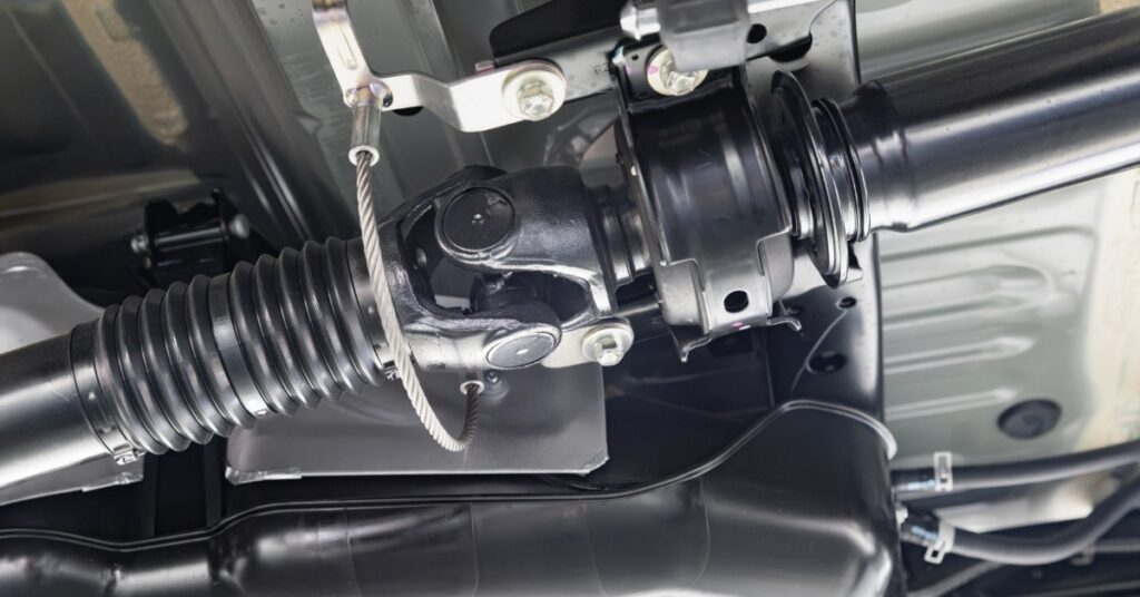
Universal joints (U-joints) connect driveshaft sections that meet at changing angles inside mining machinery. Each cross-shaped joint carries torque through four bearing caps while the driveline moves with chassis articulation. That compact movement protects power transfer between components that don’t remain perfectly aligned during operation.
Heavy loads place concentrated pressure on the cross trunnions and needle bearings. Poor lubrication or incorrect geometry then turns normal contact into accelerated wear. Crews prevent premature wear on driveshaft U-joints by controlling the service conditions that shape bearing life.
Use the Correct Lubricant
Grease forms a protective film between each trunnion and its needle bearings. The film reduces friction while carrying heat away from loaded contact surfaces. Once the lubricant breaks down, metal contact scores the trunnion and flattens the rollers.
Technicians must follow the driveshaft manufacturer’s grease specification during every service. An incompatible formula weakens the existing lubricant or restricts movement inside the journal cross assembly. Therefore, crews shouldn’t select grease through color or texture alone. Pay attention to previous service records to identify the exact product used during each lubrication cycle.
Match Intervals to Mining Conditions
Calendar dates don’t reflect every operating condition underground. Water exposure and abrasive dust shorten lubricant life between planned services. High joint angles also increase bearing movement and heat during each shaft rotation.
Maintenance teams must adjust the interval around machine duty. Repeated articulation or frequent washdowns call for additional inspections between scheduled services. Crews can coordinate U-joint work with nearby powertrain maintenance.
However, dry seals or discolored grease show that the previous interval ran too long. Record water exposure and recent articulation demands after each inspection. Those notes explain why one machine consumes grease sooner than another.

Clean Fittings Before Greasing
Grease guns push surface contamination straight into the bearing caps. Underground grit then enters a space with very small rolling clearances, and particle interrupts the lubricant film and scratches the surfaces carrying torque.
Before connecting the coupler, wipe the fitting and the area around its base. Use clean material that won’t leave lint near the opening. Inspect the grease gun tip because a dirty coupler contaminates every joint the crew handles during the shift. Replace damaged fitting caps after lubrication ends to protect the opening between service events.
Purge Every Bearing Cap
Fresh grease must reach the entire journal cross assembly. Filling only one side leaves old lubricant inside another bearing cap. As a result, one dry trunnion may continue wearing after the service record shows completed lubrication.
Apply grease at controlled pressure until fresh material appears from all four seals. Watch each cap because an uneven purge signals a blocked passage or damaged seal. Excess pressure won’t solve a restriction and might damage the seal. Stop the process until the grease path receives inspection.
Protect Seals During Cleaning
U-joint seals store grease inside the bearing caps while blocking water and grit. Washing with direct pressure can lift a seal edge and drive moisture into the bearing. Additionally, aggressive cleaners damage sealing materials and weaken protection around each bearing cap.
Avoid directing pressurized water or steam at driveshaft joints. Use a low-pressure rinse combined with a soft brush or lint-free cloth to remove packed debris from around the seals and bearing caps. After washing, inspect each seal for torn lips or displaced rings.
Preserve Driveshaft Phasing
Phasing keeps the yokes in a precise, engineered alignment so both universal joints rotate in sync along the driveshaft. When technicians maintain this alignment, each joint shares angular movement evenly, resulting in stabilized torque transfer and reduced cyclic speed variation. If a slip section goes back together out of phase, the shaft develops uneven rotational speeds that quickly translate into vibration, noise, and accelerated wear on the cross and bearings.
Locate the factory timing marks on the yokes and slip assembly. Be sure to align the marks exactly as the manufacturer specifies. Before separating any components, technicians should scribe additional reference marks on both the shaft and slip yoke, especially when factory markings have faded from wear or contamination.
During reassembly, keep the splined sections in the same orientation they had before disassembly. A disciplined approach ensures the joints rotate in phase, prevents unnecessary stress on the new cross, and eliminates vibration that lubrication or routine servicing cannot correct.

Verify Flange Fit and Fasteners
Flange faces position the driveshaft at each connected unit, so technicians must ensure these surfaces sit perfectly clean and aligned. Dust, paint, or grease on the mating faces prevents full contact and immediately introduces runout in the assembly. When this happens, the bolted connection loses stability and the driveline can no longer maintain proper alignment.
Clean each flange face and center diameter to remove all contaminants. Then, inspect the pilot fit to confirm the components seat correctly without interference. To verify alignment before tightening the components, check the mounted flange for both radial and axial runout.
Once alignment checks pass, technicians must install the correct bolt. Tighten the fasteners in a crosswise pattern to distribute load evenly across the flange. Finally, use a calibrated torque wrench to apply the correct preload and prevent uneven clamp force that could compromise the connection.
Keep Joint Angles Within Their Limits
U-joint problems often start when the driveshaft runs at excessive angles. As the angle increases, the joint is incapable of sustaining balanced bearing movement. Instead, each trunnion forces uneven load shifts through the bearing caps, which generates heat and accelerates wear on the rolling surfaces.
This issue usually develops gradually. Worn engine mounts and shifted powertrain alignment can all push the driveline out of its intended geometry. When this happens, the joint works hard on every rotation.
Measure alignment against the manufacturer’s specifications rather than assuming the setup remains correct. Check the installed angle and compare it to the approved limits for the specific operating speed. If there is excessive deflection, correct the alignment immediately to restore proper operating conditions and prevent further damage.
Complete Repairs With Proper Support
Disciplined service will prevent premature wear on driveshaft U-joints across demanding mining cycles. It’s essential that the selected replacement U-joints match the driveshaft series and original assembly requirements. Incorrect bearing dimensions alter internal clearance, while reusing damaged fasteners on split bearing designs weakens the repaired connection.
Some driveshaft repairs require balancing after cross replacement. This step becomes critical when shaft speed exceeds the manufacturer’s repair limit. Bull Powertrain supports mining teams that service GWB industrial driveshafts and related powertrain components. Genuine parts and experienced repair support preserve the intended fit across the driveline.