
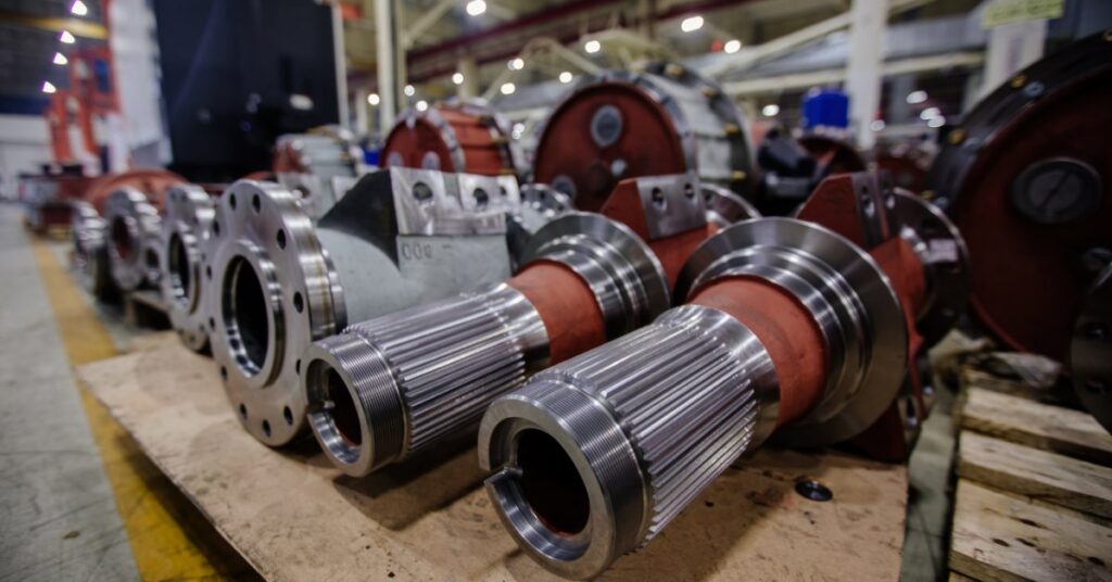
Mining machines carry heavy loads through uneven headings, tight turns, and changing ground conditions. A rigid axle connection would push excessive stress into the housing and frame joints as the machine moves through those conditions.
Axle oscillation controls this stress through a guided pivot motion. The design lets the axle follow uneven ground while the machine structure carries weight through a predictable load path. Comparing integrated and central oscillation for Kessler axles will help you choose the correct design for your mining machinery.
What Does Axle Oscillation Do?
Oscillation lets an axle rotate through a limited arc across the machine’s width. One wheel end rises over uneven rock, while the opposite side drops into a low area. Guided movement keeps the housing from twisting randomly under a loaded machine, protecting the driveline’s geometry during travel.
Universal joints work with input yokes and planetary hubs as axle movement remains within the intended range. Oscillation supports traction by keeping tire contact aligned with the ground profile.
Consistent tire contact becomes especially valuable as the machine crosses a rut or ridge. Once the axle loses stable contact, the machine works tirelessly. The operator might notice harsh feedback through the machine before a damaged part ever reaches failure.
Why Does Pivot Location Alter the Machine’s Performance?
Pivot location changes how the axle shares force with the machine structure. The pivot defines the path the load takes from the tire contact patch into the axle housing and frame. A small change in pivot placement changes how the assembly handles roll motion.
An integrated design places the oscillating function close to the axle package. A central design uses a defined pivot area near the middle of the mounting structure. Both approaches control axle movement through different layouts.

Integrated Oscillation
Integrated oscillation builds the pivot function into the axle package. The housing works with bearing supports and mounting features as a compact unit. Engineers use this layout in machines with tight drivetrain envelopes.
The motion source sits near the axle itself. Instead of relying on a large separate cradle around the axle, the package carries much of the oscillation function within its own structure. Crews see a tight relationship between the housing and pivot hardware during inspection.
Compact Axle Packaging
Compact packaging has value in underground machines because space around the driveline fills quickly. Brake assemblies compete with steering cylinders and frame plates. Guards and driveline shafts add further clearance limits around the axle.
An integrated oscillation layout groups the pivot function close to the axle, reducing the amount of separate mounting structure around the housing. The axle still moves with the ground while the pivot hardware remains close to the component it controls.
Load Movement
In an integrated layout, load enters through the tires and moves into the axle housing. The housing resists bending while the pivot hardware manages rolling across uneven ground. This creates a direct relationship between axle strength and oscillation behavior.
The arrangement limits uncontrolled twist because the pivot function remains close to the housing. As the machine crosses uneven rock, the axle moves through its allowed arc and sends force into the mounting points. Proper fit and steady lubrication keep movement controlled because both conditions protect bearing surfaces under repeated load cycles.
Application Fit
Integrated oscillation suits machines where compact structure counts and the axle assembly forms a major part of the motion system. Underground loaders often use this arrangement because the axle, pivot features, and surrounding frame structure work together within a limited installation envelope. The design aligns well with equipment built around axle movement near the housing rather than a separate central support.
Selecting the right configuration starts with the original machine layout. Axle load and brake layout influence the available space around the housing and shape how the oscillation system fits within the chassis. Tire size and driveline angle further influence the choice through clearance requirements and operating angle limits. Reviewing these factors early in the specification process reduces the risk of fitment issues during installation and operation.
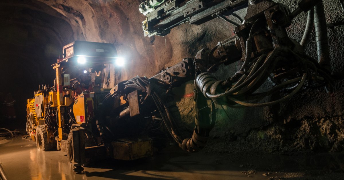
Central Oscillation
Central oscillation uses a pivot point in the middle of the axle mounting arrangement. The axle rotates around a central support, like a trunnion or cradle structure. This layout separates the main pivot relationship from the outer wheel ends and places motion control at the center.
The design provides the machine frame a defined area where oscillation loads enter. The axle still carries torque and wheel-end load. The central pivot governs the housing roll across uneven ground.
Central Pivot Structure
A central pivot structure provides a clear axis of movement. The axle housing rotates around the center support while the frame controls travel. Stops or mounting geometry limit the arc, so that the axle resists over-rotation during severe ground changes.
Load Movement
Tire force moves into the axle housing and then toward the center pivot in a central design. The pivot carries repeated roll motion as the machine travels across uneven ground. Load concentration at the center demands strong bearing support and a precise fit between the axle and cradle.
A central pivot handles heavy motion cycles when lubrication and alignment remain within specification. Poor fit changes the load path and pushes stress into surrounding mounts. Loose movement causes tire scrub or harsh driveline reaction during loaded turns.
Application Fit
Central oscillation suits equipment designed around a strong center support. Haulage machines use this layout when the frame directs axle movement through one pivot zone. The design suits machines with enough structure around the axle center to carry rolling forces.
The layout supports predictable inspection routines because most wear evidence appears near the central support. Crews return to the same pivot surfaces during scheduled service, which makes bearing replacement and seal work easier to plan. Stable inspection patterns support planned rebuilds before excess movement spreads into the frame.
Support The Axle Through Service
Comparing integrated and central oscillation shows how each design manages axle movement through a different pivot layout. Both designs let the axle follow uneven ground while the frame continues to carry the load through the machine structure.
Bull Powertrain supports hard rock underground mining operations with quality Kessler parts and service knowledge rooted in heavy-duty driveline work. Contact our team when axle movement or rebuild timing requires experienced support.